Static Discharge Kit Installation for Retro units
The only tool required is a medium Phillips screwdriver.
This process should only take about 10-15 minutes.
Overview: It has come to our attention that some customers have been experiencing
static build up on their film. This static discharge can be caused by a variety
of things such as atmospheric conditions, type of film, type of film cleaner,
film tension, type of reels (metal vs. plastic), etc. Because the conditions that
cause static discharge vary, most customers have no issues. While not dangerous,
the discharge can cause blue LEDs to burn out prematurely or blink,
registration issues, and interference in logic and motor functions of the internal circuitry.
This static discharge kit will eliminate those issues.
If you work in an area that is prone to static build up, it is advised (but not required)
to also use an anti static cleaner to wipe down all metal parts of the film path at the
beginning or end of each work day. There are many brands and availability may differ
by country. Here is one suggestion:
http://www.aclstaticide.com/staticide_wipes.html
Installation Procedure
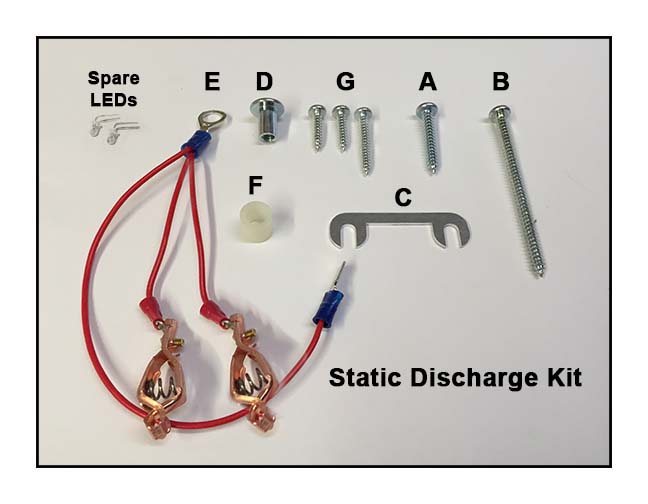
Open your kit and locate the above parts.
NOTE: The Spare LEDs will not be used in this installation but are
provided in case they are needed now or in the future.
Unplug the USB and power cables from the unit.
Remove 4 corner screws and remove back cover.
Remove the left black retainer screw from the gate as shown.
Replace black retainer screw with long silver screw "G" and tighten until snug.
(Do not confuse this screw with the thicker silver screw "A")
NOTE: As you thread screw into place, watch the back side of the panel to
make sure that screw tip does not hit heat sink on LED bar. If heat sink is in
the way, just rotate to clear the tip of screw.
Remove black right hand guide screw.
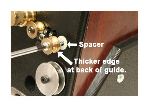
Insert silver screw "A" into right guide as shown. Do not tighten completely.
Some units have a spacer behind the guide and some do not.
Note the spacer position (if present) and that the thicker edge of the guide is at the back.
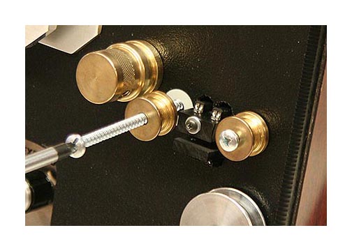
Repeat process using silver screw "B" for left guide.
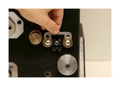
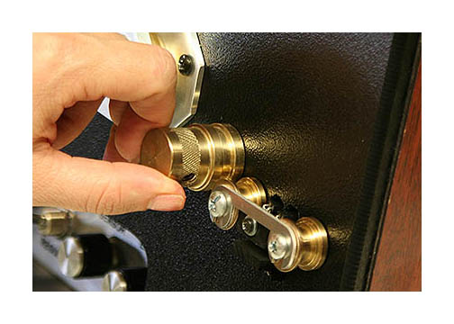
Insert bridge plate "C" between front of guides and screw heads.
Some plates have a finished side and a rough side.
It will look nicer if the finished side is facing front.
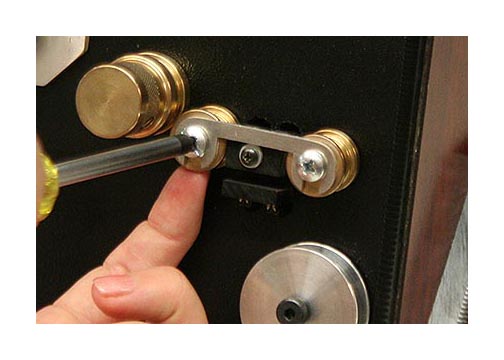
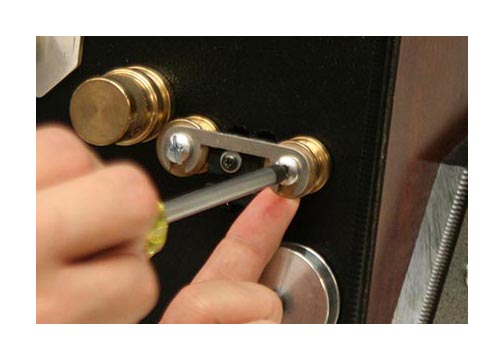
Gently push up on each guide and hold in place as you tighten the two screws.
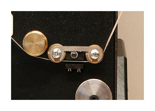
Note that the film under tension is closer to the top of the sensor block than the bottom.
The film should be as close as possible without touching the top of the sensor block.
If the film is too high or too low, then adjust the guides and sensor block accordingly.
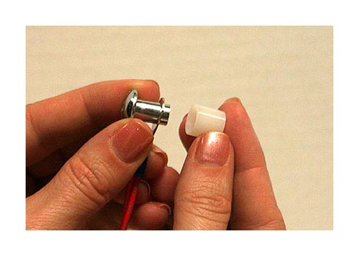
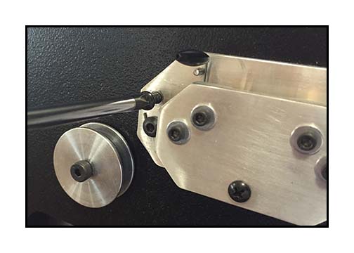
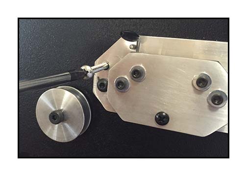
Insert silver end cap "D" into grounding strap "E" as shown.
Place nylon spacer "F" onto end of cap.
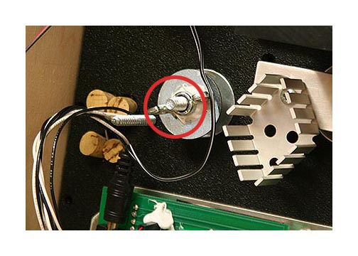
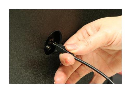
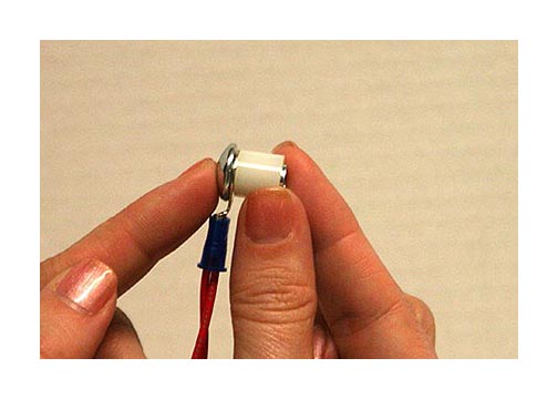
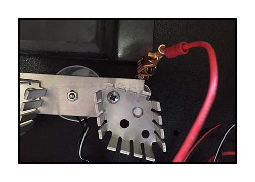
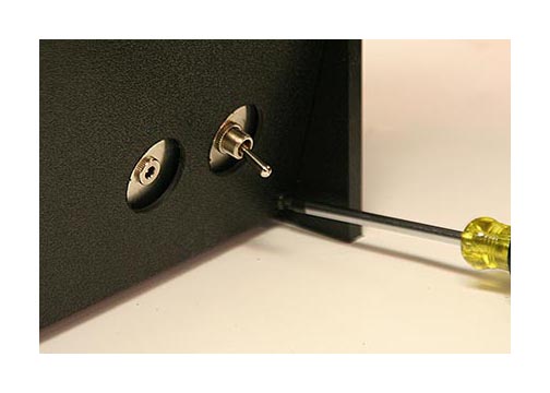
Locate the threaded shaft circled in red on the back of the framer knob.
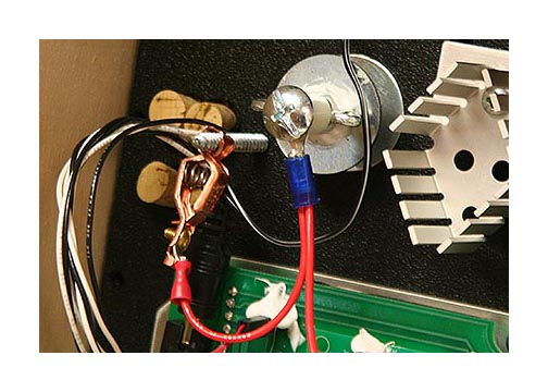
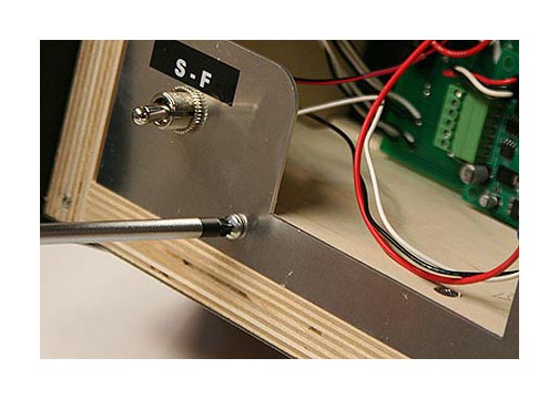
Screw the end cap "D" onto the threaded shaft as shown and attach clip to silver screw "B".
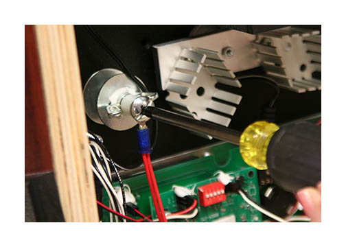
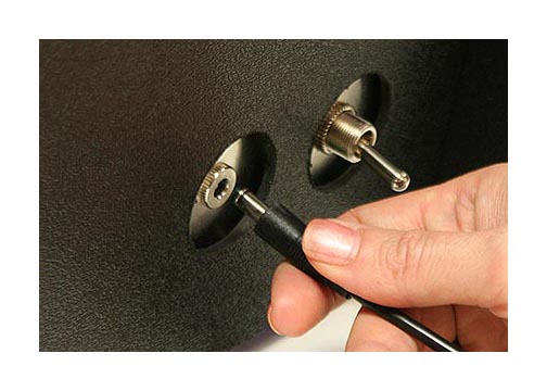
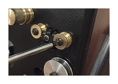
Hold the framer knob with one hand and gently tighten the end cap "D" with a screwdriver.
It should just be snug and the grounding strap "E" should hang loose.
Attach other clip to long silver screw "G" previously installed.
NOTE: Depending on the model, you may have to attach to the end of the screw
or the body of the screw nearer the panel. Just make sure that the wire is
clamped securely and won't accidentally come loose.
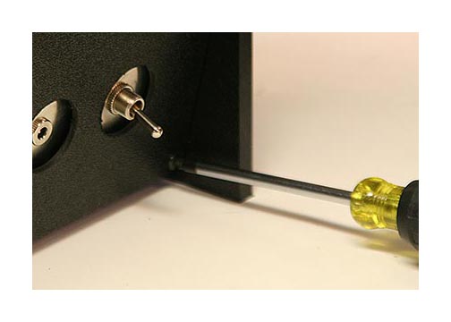
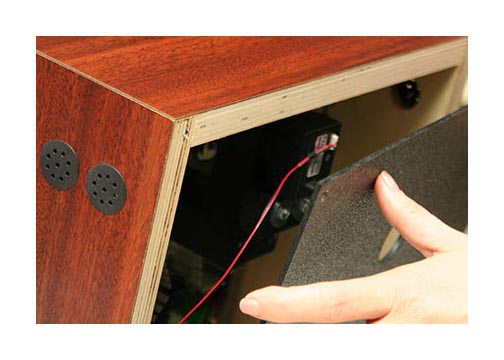
Remove the left retaining screw on the rear metal plate and replace with short silver screw "G".
Do not tighten completely.
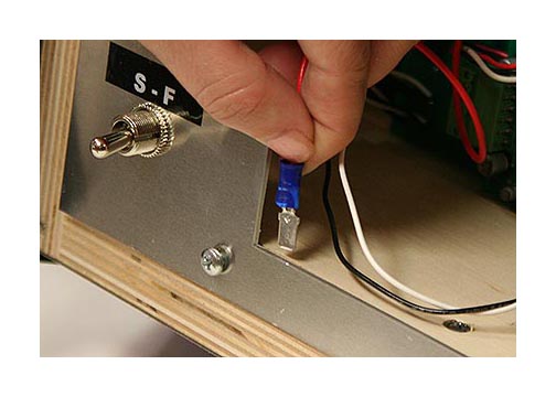
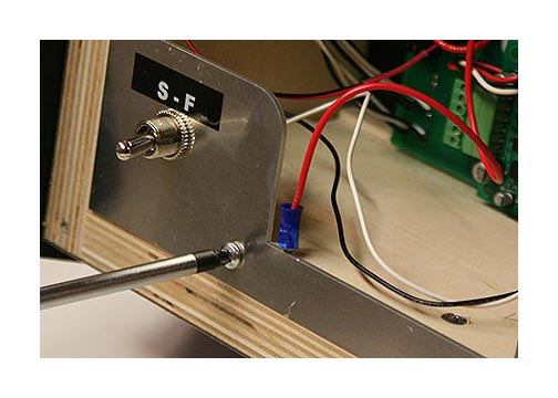
Insert end of grounding strap "E" between metal plate and wood base as shown.
Tighten short silver screw "G" until snug. If desired, you can also replace the
right retaining screw with remaining silver screw "G".
Replace rear cover and tighten screws.
Your installation is now complete!
If you have any questions, please email us at moviestuff@swtexas.net or call 830-966-4664.