WorkPrinter-16 Set Up
You will need a Mac or PC with three internal drives.
One drive should be your system drive and the other two should be set up
in a Raid-0 drive array. Failure to use an internal Raid-0 array can result
in a loss of sync on the captured file.
For the Mac, you will need the CaptureMate software.
For the PC, you will need CineCap software.
Both are available only to MovieStuff customers that
have received their WorkPrinter units shipped directly from MovieStuff.
Please email us with the
name and email address that was on the order form used to purchase the
WorkPrinter unit and we will email you the private purchase link for either
the CineCap or CaptureMate software. To maintain your warranty and customer
support, we ask that you please do not publically post this purchase link
on the web. Thanks.
NOTE: Some video cameras have difficulty white balancing to the new
daylight balanced LED light source. If your image is too blue and you have
already switched your camera to its daylight setting, then simply use an
85B conversion filter on the front of your camera lens. This will convert
the daylight LED light source to tungsten balance. Your camera can then
be white balanced in either the daylight or tungsten setting, depending
on which provides the best results.
NOTE REGARDING POWER FOR 50Hz operation:
This unit will not operate directly on 230 volt power.
For international operation, you will need a transformer rated at about
250 watts capable of providing 115 volts AC. As transformers are notoriously
inaccurate in their labeling, please measure the voltage of your transformer
to be sure that it does not put out more than 115VAC at 50Hz. If
in doubt, please contact MovieStuff at 713-863-7384 for specific help with
this issue. I recommend this transformer:
http://www.jaycar.co.nz/productView.asp?ID=MP3080&CATID=&keywords=transforme
After unpacking your unit, please account for the following
items:
A) The synch mouse
B) The synch cable
C) The projector
D) The condenser lens
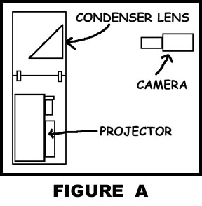 Connect
the two halves of the baseboard and secure with the latches provided. Mount
the condenser lens on the baseboard as shown in figure A.
On some units, there may be three spacers or washers that go under the
condenser lens. Insert beneath condenser lens and attach with the provided
screws. Be careful not to tighten too much or you risk breaking the plastic
base of the condenser lens.
Connect
the two halves of the baseboard and secure with the latches provided. Mount
the condenser lens on the baseboard as shown in figure A.
On some units, there may be three spacers or washers that go under the
condenser lens. Insert beneath condenser lens and attach with the provided
screws. Be careful not to tighten too much or you risk breaking the plastic
base of the condenser lens. 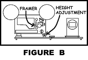 Once attached, the condenser lens should face out toward the camera as
seen in figure B. Note the framer adjustment tab near the
gate of the projector as well as the height adjustment foot on the front
of the unit. They will be used later to fine tune the placement of the
image in the center of the condenser lens.
Once attached, the condenser lens should face out toward the camera as
seen in figure B. Note the framer adjustment tab near the
gate of the projector as well as the height adjustment foot on the front
of the unit. They will be used later to fine tune the placement of the
image in the center of the condenser lens.
Place the camera in manual focus and the zoom on wide
angle and start with the camera about 1 foot from the condenser lens. Avoid
using the built-in LCD monitor of the camera and always feed the video
of the camera to a full size monitor to allow for critical alignment. The
camera should have a minimum of a 10x optical zoom for best results and
should be mounted on a sturdy tripod equipped with an adjustable column
head for incremental vertical adjustments. Level the camera so that the
camera lens is centered on the condenser lens. Plug in the projector
and turn the control knob to the PLAY position. 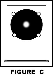 If
the motor starts,
If
the motor starts, 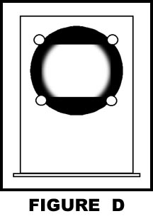 turn
it off by pressing the red MOTOR button. Press the red LIGHT button and
adjust the alignment of the camera until you see a small white dot in the
middle of the condenser lens as illustrated in figure C.
Next, slowly pull the camera away from the condenser lens, keeping the
white dot in the center. As you pull back, the white dot will grow in size,
starting to reveal the edges of the gate as seen in figure D.
As you continue pulling away, you will be able to see the entire rectangular
gate but will need to constantly keep the camera aligned both vertically
(using the column adjustment) as well as side to side (move the entire
tripod; not panning) while pulling the camera back. Once the entire gate
is visible, lock the camera into position.
turn
it off by pressing the red MOTOR button. Press the red LIGHT button and
adjust the alignment of the camera until you see a small white dot in the
middle of the condenser lens as illustrated in figure C.
Next, slowly pull the camera away from the condenser lens, keeping the
white dot in the center. As you pull back, the white dot will grow in size,
starting to reveal the edges of the gate as seen in figure D.
As you continue pulling away, you will be able to see the entire rectangular
gate but will need to constantly keep the camera aligned both vertically
(using the column adjustment) as well as side to side (move the entire
tripod; not panning) while pulling the camera back. Once the entire gate
is visible, lock the camera into position.
Next, place a take up reel on the take up spindle of the
projector. Turn the control knob back to the STOP position but leave the
lamp on. 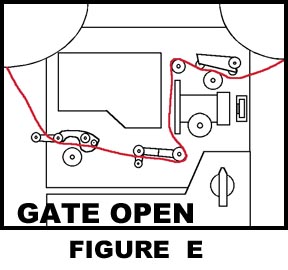 Locate
some disposable film
Locate
some disposable film 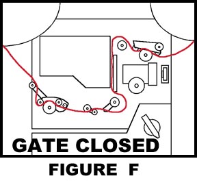 that
you can use to practice loading with and refer to figure E
for the appropriate threading path. This unit is a slot load, so the film
enters from the side but MUST pass around the various rollers as indicated.
Thread the film leader onto the take up reel and turn the take up reel
by hand several times to make sure that you get a good wrap. Turn the control
knob to PLAY and note the rollers as they change their positions relative
to the film. The rollers and film path should now appear as illustrated
in figure F.
that
you can use to practice loading with and refer to figure E
for the appropriate threading path. This unit is a slot load, so the film
enters from the side but MUST pass around the various rollers as indicated.
Thread the film leader onto the take up reel and turn the take up reel
by hand several times to make sure that you get a good wrap. Turn the control
knob to PLAY and note the rollers as they change their positions relative
to the film. The rollers and film path should now appear as illustrated
in figure F.
Briefly press the red MOTOR button and observe the film
as it passes through the unit. If the projector loses its loop (the film
draws tight and chatters), stop the motor and turn the control knob to
STOP and then back again to PLAY. Start the motor again and everything
should run smoothly. Now, stop the motor but leave the control knob in
the PLAY position. Ideally, you would like a clean frame with good contrast
visible in the gate of the projector. If the film stops mid-frame, "bump"
the red MOTOR button until a frame lands clearly in the gate. Zoom the
camera into the condenser lens and focus. Use the FRAME ADJUSTMENT and
HEIGHT ADJUSTMENT as seen in figure B to center the frame
in the middle of the condenser lens.
 At
this
At
this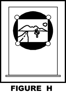 point, the
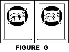
image may have a "bow" in the frameline as seen in figure G.Adjusting
the focus of the PROJECTOR will subtly change the size and shape of the
image, allowing the framelines to be corrected until they are straight.
Even if this action causes the image to go out of focus, do not worry.
The focus can be reestablished at the camera. Once corrected, the framelines
should be straight across and illumination even from corner to corner with
the focus sharp across the entire image as seen in figure H.
point, the
image may have a "bow" in the frameline as seen in figure G.Adjusting
the focus of the PROJECTOR will subtly change the size and shape of the
image, allowing the framelines to be corrected until they are straight.
Even if this action causes the image to go out of focus, do not worry.
The focus can be reestablished at the camera. Once corrected, the framelines
should be straight across and illumination even from corner to corner with
the focus sharp across the entire image as seen in figure H.
Next, connect the synch mouse to the computer and attach
the synch cable to the mouse on one end and the other end to the SYNCH
socket found on the projector. Set up your computer for STOP MOTION CAPTURE
using the appropriate software and leave the mouse button hovering over
the on-screen capture button. Prime the computer by clicking off the first
frame manually. Then, press the red MOTOR button and start the projector
running. Click on the SYNCH SWITCH on the projector and the on-screen mouse
should start capturing frames. Once completed, review the captured footage.
If you see any vertical blurring in the frames, then the timing of the
projector needs to be adjusted. 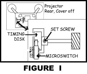 Remove
the multiple screws along the edge that hold the back cover in place and
remove the back cover carefully. The TIMING DISK is found near the front
of the projector and partially protrudes near the lens. As seen in figure
I, there is a set screw on the TIMING DISK that can be loosened
with an allen wrench. Hold the center shaft and rotate the TIMING DISK
a bit then tighten the set screw in place. Transfer some more film and
review the footage. If the streaking gets better, then continue rotating
the TIMING DISK the same direction. If the streaking gets worse, continue
the opposite direction. Eventually, the transfer should be clear of any
streaking frames. Apply the appropriate speed change and let the footage
render. The end result should be a crystal clear transfer with no visible
flicker and good focus and illumination from corner to corner. If you have
any questions, please feel free to email
us or give me a call at 830-966-4664.
Remove
the multiple screws along the edge that hold the back cover in place and
remove the back cover carefully. The TIMING DISK is found near the front
of the projector and partially protrudes near the lens. As seen in figure
I, there is a set screw on the TIMING DISK that can be loosened
with an allen wrench. Hold the center shaft and rotate the TIMING DISK
a bit then tighten the set screw in place. Transfer some more film and
review the footage. If the streaking gets better, then continue rotating
the TIMING DISK the same direction. If the streaking gets worse, continue
the opposite direction. Eventually, the transfer should be clear of any
streaking frames. Apply the appropriate speed change and let the footage
render. The end result should be a crystal clear transfer with no visible
flicker and good focus and illumination from corner to corner. If you have
any questions, please feel free to email
us or give me a call at 830-966-4664.
Roger Evans